MARCEE Minnesota Area R/C Electric Flight Enthusiasts Articles & Reports
Astro 010 Experience (Including Geared)
This is not a comprehensive test. I got the Astro 010 while traveling during the winter and I also got invited to fly indoors but found out the night before that the plane I was going to fly was too heavy.
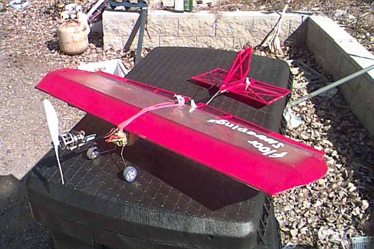
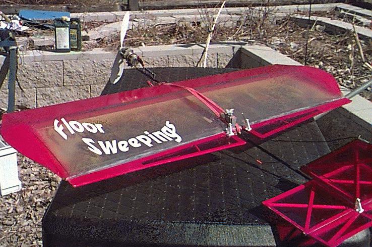
So in one evening I built "Floor Sweepings" out of mainly carbon fibre and anything else I already had including 3 kinds of covering etc. "Floor Sweepings" is the plane pictured with the Astro 010 below.
(A construction section for "Floor Sweepings" will be added later)
All runs were with 8 - 350 mah Cells: My intent is to use the Astro 010 on fairly high performance mini sport planes so the on / off throttle is just fine.
All the below flights were done outdoors in 5-10 mph wind.
First Scenario / Flight - Astro 010 with supplied 5.5X2.5 Prop. This is a gutsy little motor. The performance was very good. Motor Runtime until noticeable sag was 5 min. Assuming the batteries were up to capacity that means an average of 4.2 amps. Which is higher than recommended by Astro Bob or Doug Engraham - Probably should use 7 Cells with the supplied prop. The plane was quick and responsive, pulled through loops and rolls well.
-- Side note, the Gunther / zagi prop (nominally 5X4) also works well on 7 cells.
Second Scenario / Flight -Astro 010 with a Cox 5X3 Prop. Wow, much better, the plane was faster and "hyper active" Not quite as steep of sustained climb angle, but good. For a sport plane, I like the Cox 5X3 much better. Motor Runtime until noticeable sag was 6 min. Again assuming the batteries were up to capacity that means an average of 3.5 amps. This is right at the top of the Astro recommendation.
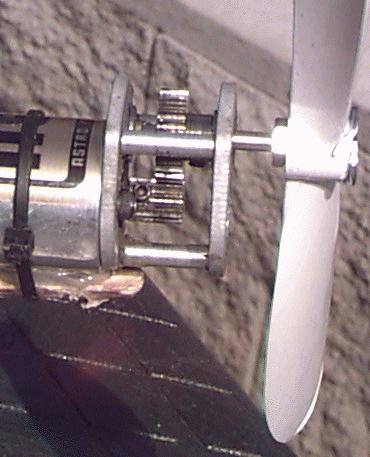
Third Scenario / Flight - Astro 010 2.25:1 Gear (MPI Unit) . Gunther 7X6 (Titanic drive prop). Wow Wow Wow. Great performance significantly better climb than the two straight drive props. Motor Runtime until noticeable sag was 7 1/2 min. Again assuming the batteries were up to capacity that means an average of 2.8 amps. This is well within the motor controller recommendation !! And the best performance.
Gear Box Description & Pictures / Specifications
Most speed 400 gear boxes will mate up to the Astro 010/020/050 brushless motors. So at first I just figured I would drill out the bore on a MPI Maxx pinion and I would be all set.
Problem, the motor shaft is so short on the 010 that the set screw/hub side must be towards the motor which gave alignment problems with the standard gears for the MPI Maxx.
So I converted mine to standard 48pitch R/C Car pinions a 12Tooth for the motor shaft and a 27tooth for the driven (27/12 = a ration of 2.25:1). Both come standard with 1/8" bore. I cut some short lengths of 1/8" ID Brass tubing to fit inside the bearings to reduce them to 1/8" bore. I used a R/C Airplane 1/8" axle shaft as the output (driven) gear box shaft and the Gunther 7X6 propeller. These gears were thinner and I had no problem lining them up. (Note: If you wanted to and had the tools to do it accurately, you could shorten the gearbox assembly by cutting off and rethreading the 3 spacers that hold the two gearbox faces.
Make sure you have the ball bearing MPI Maxx Gearbox. The bushing model is too inefficient. Use light oil like 3 in 1 and lube prior to flight. Set the gear fit so that you can feel some clearance all the way around the pinion. This gearbox and prop add about 5/8oz over the direct drive prop and adapter.
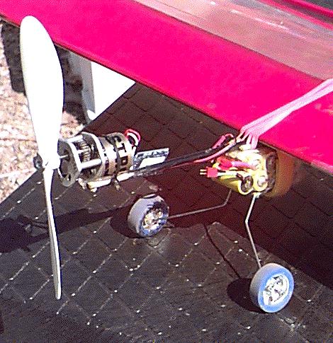
You will need to reverse the Astro 010 to run this configuration. That is very easy, just switch any two of the three wires going from the esc to the motor. I used a 2 pin deans connector so I can just unplug and plug to change directions quickly depending on the application.
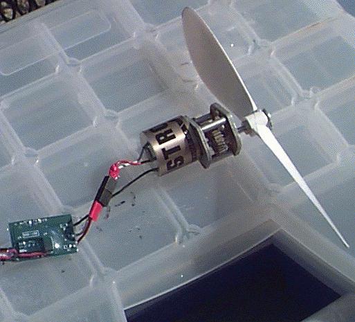
Here are some pictures (click to enlarge) showing the whole set up on "Floor Sweepings"
 Mark
1.5 -->
Mark
1.5 --> 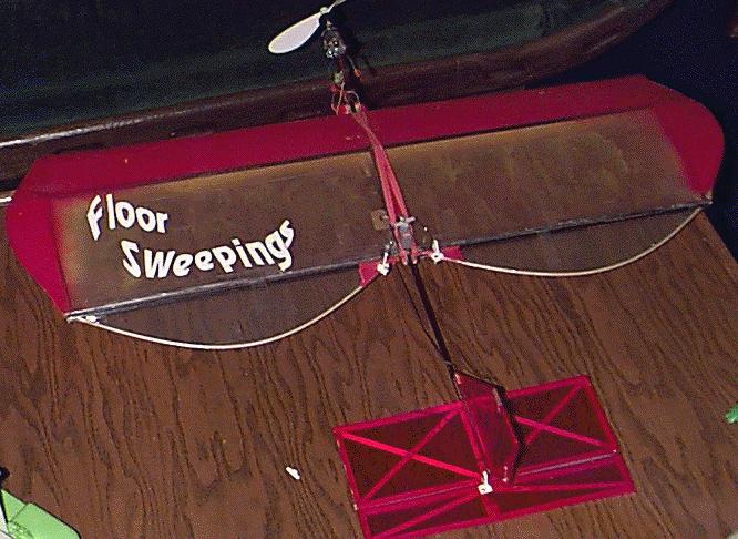
"Floor Sweepings" Specs
Span |
34" |
Length |
25" |
Weight |
11.3oz Direct / 12 oz Geared |
Area |
330sq.in. |
Motor |
Astro 010 |
Gearbox |
2.25:1 Modified MPI Maxx & 7X6 Gunther |
Cells |
Sanyo 8-350ma |
Servos |
FMA 80 |
Esc |
Astro |
Mark II "Floor Sweepings" will be about 3oz lighter and better craftsmanship and Plans will be added here as part of the article. But until I get that done and to try to answer all the questions I have been getting, here is a description on how I built the wing. Keep in mind that the MARK II wing will have some differences.
So without the benefit of pictures or drawings, I will try to describe the building of the wing The wing is all Carbon Fiber and a flat bottom airfoil.